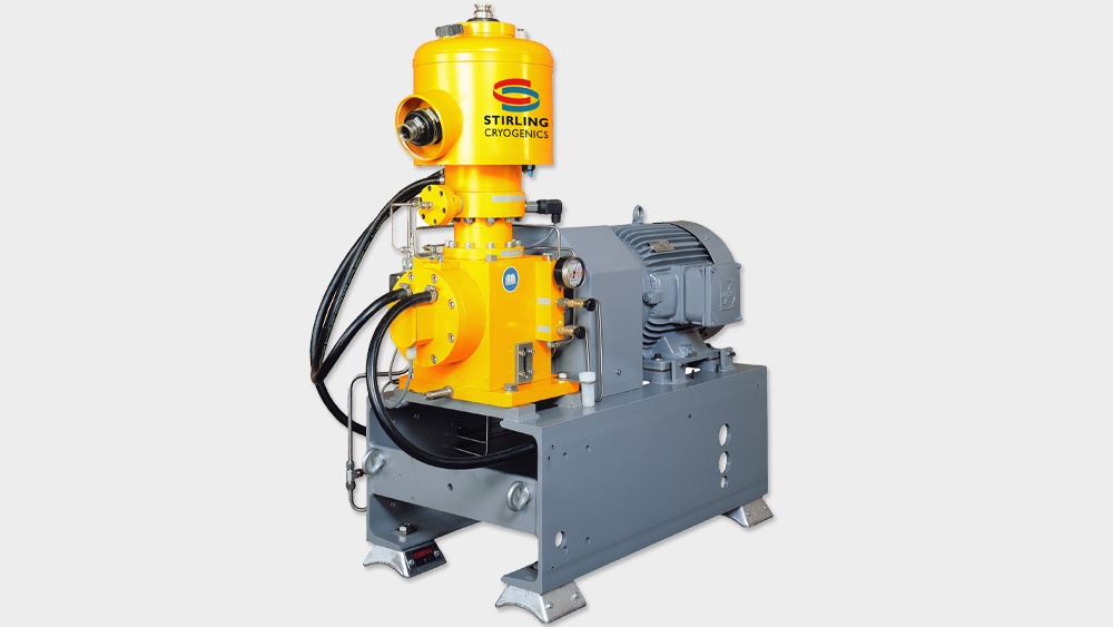
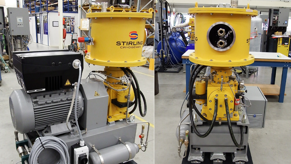
> Stirling Cryogenerators: The Core of Cryogenic Cooling Systems
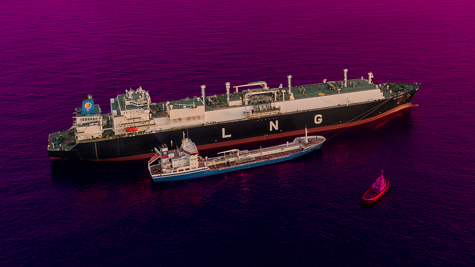
> LNG production plants
> LNG BOG management systems
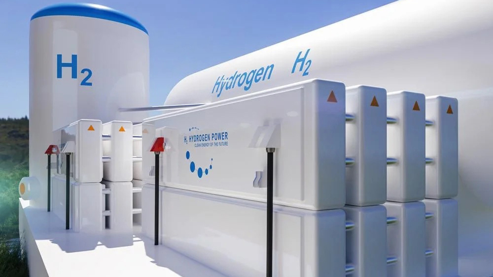
> Liquid hydrogen plants
> Liquid nitrogen production systems
> Systems for Superconductivity
> Liquid oxygen systems
> Cryogenic Closed Loop Cooling
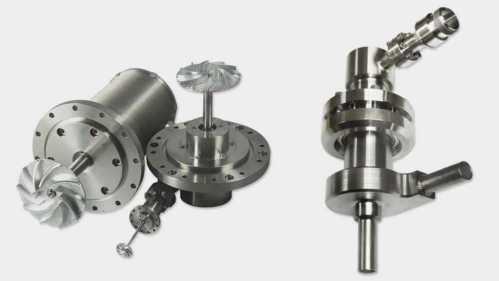
> Cryogenic fans
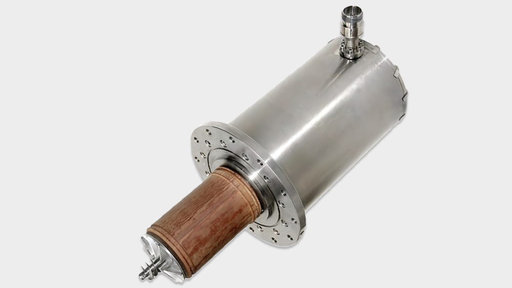
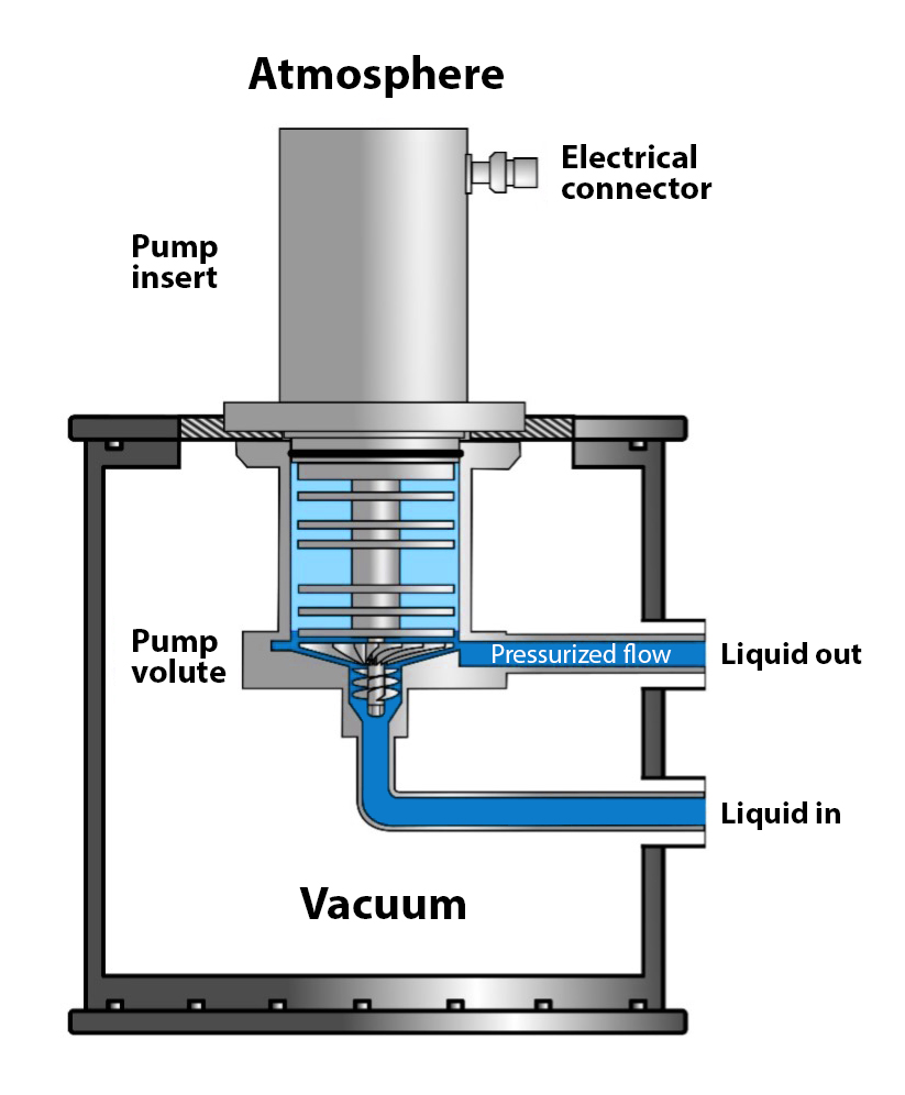
> Stirling Cryo Pump for cryogenic liquid circulation
> LNG production plants
> LNG BOG management systems
> Liquid hydrogen plants
> Liquid nitrogen production systems
> Systems for Superconductivity
> Liquid oxygen systems
> Cryogenic Closed Loop Cooling
> Cryogenic fans
> Stirling Cryo Pump for cryogenic liquid circulation
> LNG Production
> LNG BOG Management
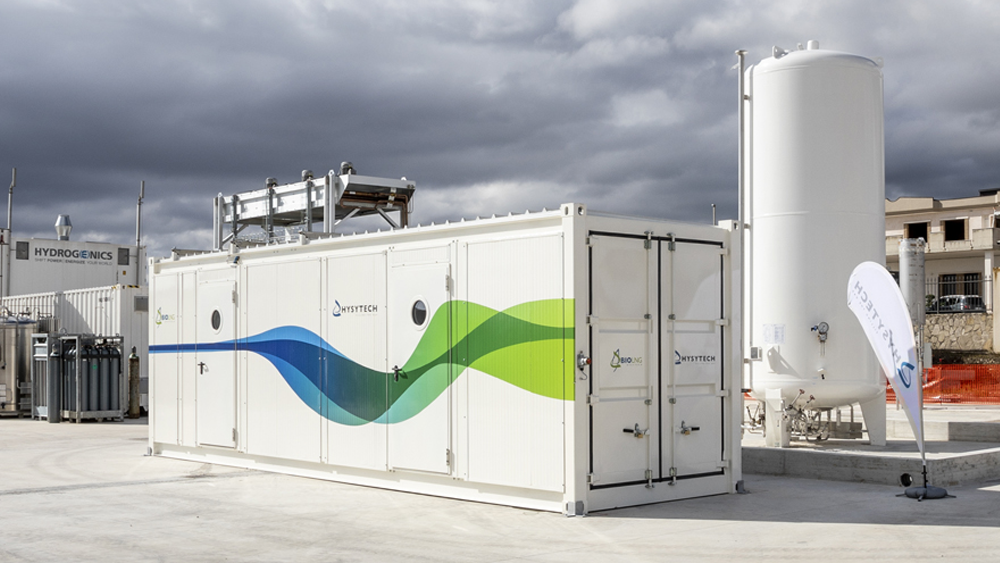
> Liquid hydrogen
> Bio Storage
> Research & University
> Healthcare
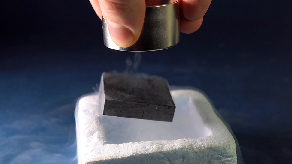
> Superconductivity
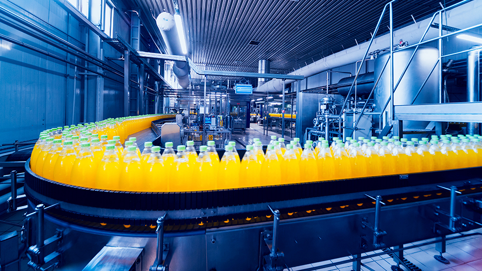
> Food & Beverage
> Aerospace
> LNG BOG Management
> Liquid hydrogen
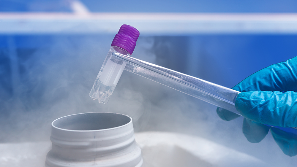
> Bio Storage
> Research & University
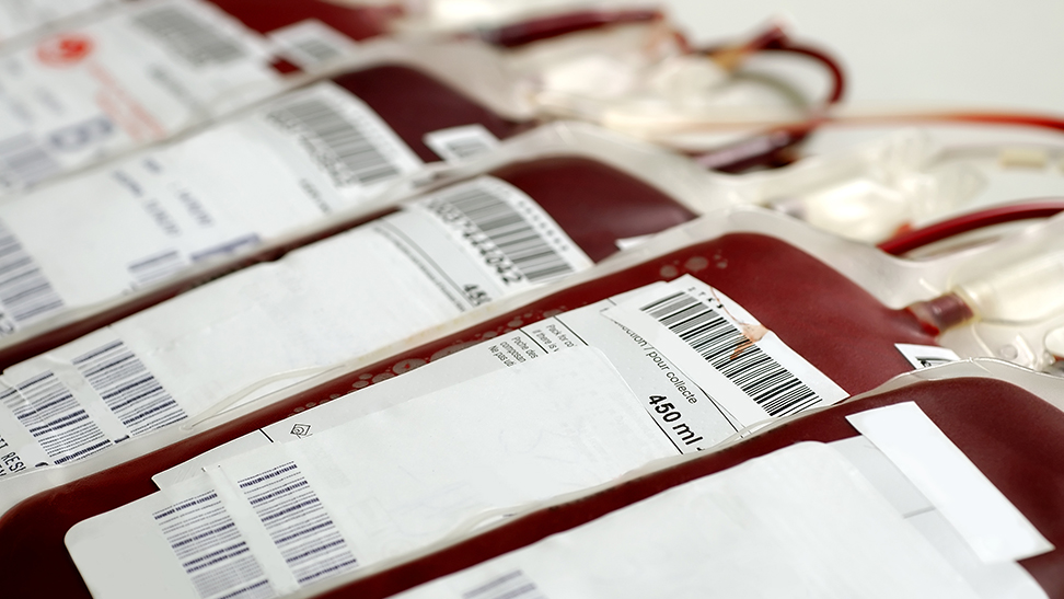
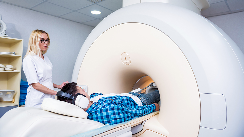
> Healthcare
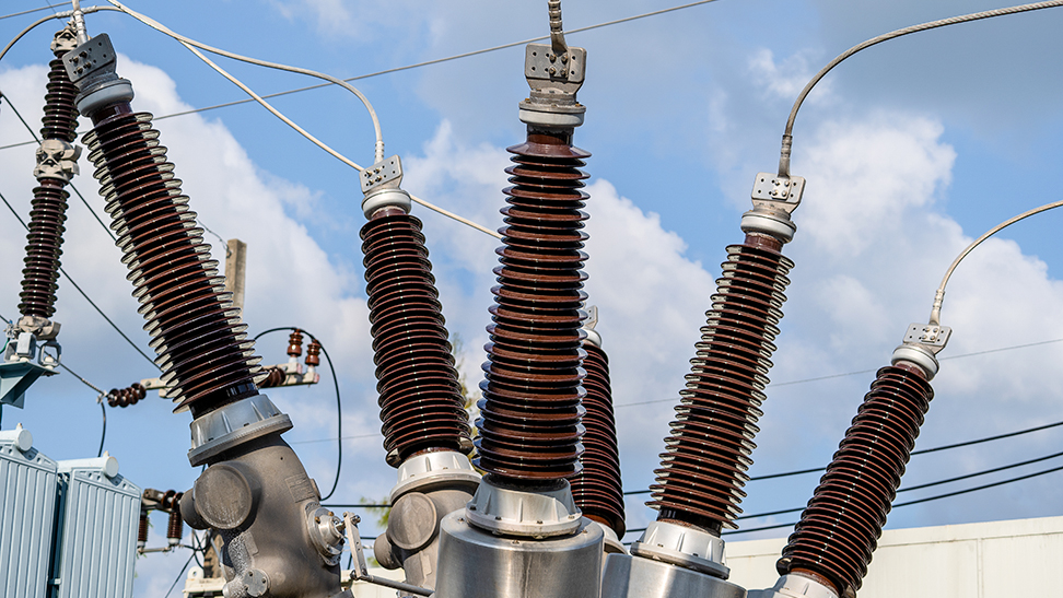
> Superconductivity
> Food & Beverage
> Aerospace
> Artificial Insemination Centre, Botswana
> La Honda, Venezuela
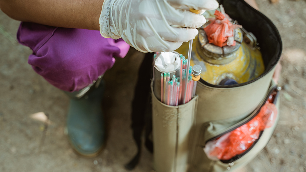
> Bovine Al, Nicaragua
> Vet Agro Sup, France
> La Honda, Venezuela
> Bovine Al, Nicaragua
> Vet Agro Sup, France
> Memorial University Newfoundland, Canada
> University of Otago, New Zealand
> CEA, Fontenay-aux-Roses France
> INFN, Italy
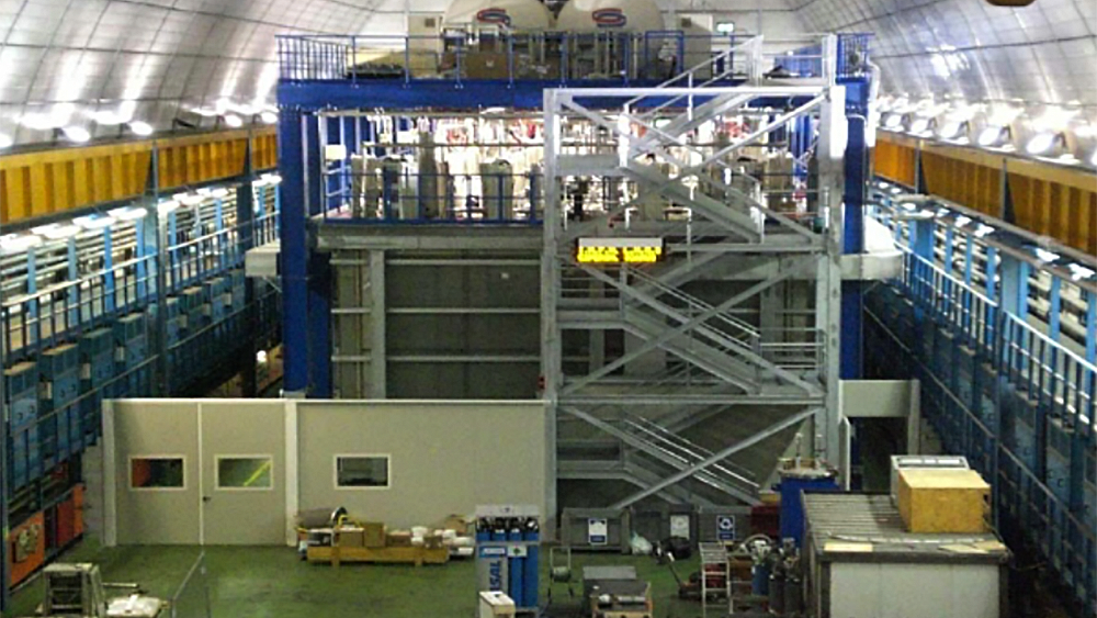
> Snolab, Sudbury Canada
> Instituto de Ecologia, Xalapa Mexico
> IVIC, Venezuela
> Isaac Newton Group of Telescopes, La Palma Spain
> Atacama Large Millimeter Array, Chile
> Nuclear site of Chernobyl, Ukraine
> RV Sonne, Germany
> RV Maria Merian, Germany
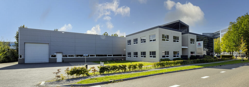
Head office:Stirling Cryogenics BV
Science Park Eindhoven 5003
5692 EB Son, The Netherlands
T +31 40 26 77 300
info@stirlingcryogenics.com
Offices in:USA
T +1 610 714 9801
usa-office@stirlingcryogenics.com
Germany
T +49 171 1795 994
germany-office@stirlingcryogenics.com
Sweden
T +46 766 111 728
sweden-office@stirlingcryogenics.com






















 .
.